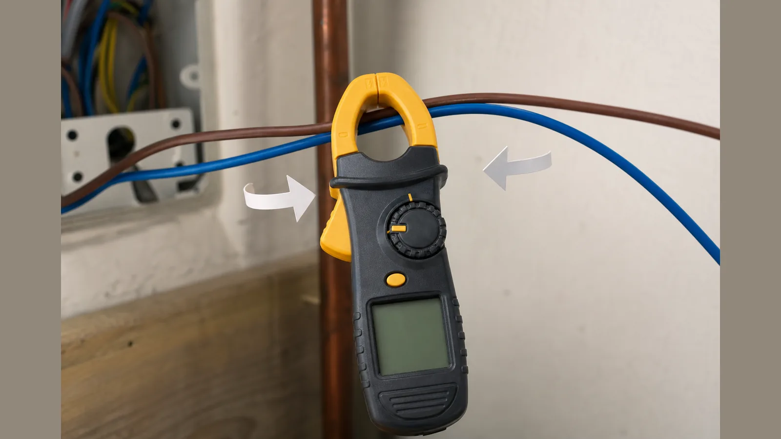
clamp meter reads zero both wires in jaw
If your clamp meter reads zero both wires in jaw, the meter is usually behaving as designed: opposing currents in live and neutral produce canceling magnetic fields, so the clamp “sees” near 0 A. Measure one insulated current-carrying conductor at a time—not the whole twin-and-earth or multi-core bundle.
Direct answer: opposing currents cancel — clamp one conductor only
A clamp meter responds to the net magnetic field around the conductor(s) inside the jaw. In a normal circuit, current out on the live and back on the neutral is equal and opposite. Put both in the jaw and those fields cancel, so the display can sit at or near zero even when the circuit is energised and loaded.
That cancellation is the same principle used when you deliberately clamp live and neutral together to look for residual (leakage) current: any reading then reflects imbalance, not load current. For ordinary load-amp checks, keep to the single-conductor rule.
- Clamp one insulated live or one insulated neutral (as your competent procedure requires).
- Do not clamp the complete sheathed cable if it still contains both go and return conductors.
- Expect near-zero or unstable nonsense readings when both conductors share the jaw—not necessarily a broken meter.
Why bundles and twin-and-earth confuse beginners
UK twin-and-earth and many appliance flexes pack live and neutral (and often earth) in one outer sheath. Clamping that outer jacket puts both current-carrying cores inside the jaw at once. The meter then reports the net ampere-turns—typically close to zero for a healthy two-wire load path—rather than the amps you expected on the live alone.
The same mistake appears on thick “main” cables and multi-core looms: the outer jacket looks like one wire, but electrically you have clamped a pair. Field troubleshooting write-ups repeatedly show near-zero displays until the user switches to a single conductor.
Related secondary cues: both conductors in clamp jaw, live and neutral cancel reading, and the single conductor clamp rule all describe this one geometry error.
Safe ways to isolate a single insulated conductor when competent
Only proceed if you are competent for the work, follow safe-isolation practice where required, and use PPE and test equipment appropriate to the installation. A clamp around insulation is non-contact with the conductor metal, but access methods that expose live parts introduce shock and arc risk.
- Prefer manufacturer-approved breakout leads, temporary test leads, or designed access points that present one insulated conductor to the jaw without removing protective covers unnecessarily.
- Where a competent person already has a safely accessible single insulated core (for example in a suitably arranged test setup), centre that core in the jaw and keep other current-carrying cores outside.
- Treat non-contact voltage indicators as orientation aids only—they do not prove a circuit is dead. Prove-dead requires the correct isolated, verified procedure for your workplace.
If you cannot present a single insulated conductor without defeating enclosures or barriers, stop and use a method suited to your competence and the installation—not improvised stripping or forced jaw access.
When you must not open enclosures
Do not remove covers, open consumer units, or expose terminals unless you are authorised and competent to do so under the applicable regulations and your employer’s procedures. Opening an enclosure to “get one wire into the clamp” is not a beginner shortcut; it can create live-part exposure and invalidate protective arrangements.
If the only way to reach a single conductor would be unauthorised panel work, leave the enclosure closed and escalate to a qualified person. Prefer measurement points and accessories intended for clamp access rather than defeating guards.
Quick checklist before blaming the meter
- Confirm you are not clamping a twin, flex, or multi-core that still contains both live and return.
- Confirm the jaw fully closes on one insulated conductor only, with no second current-carrying core inside.
- Confirm the meter is in the correct current function and range for AC or DC as applicable, and that the circuit is actually carrying current.
- If readings are zero, very low, or wildly unstable on what looks like a live cable, re-check geometry before assuming failure—common guides list exactly these symptoms for mis-clamping.
- For product features, kit contents and live pricing of a DC-capable True RMS clamp option, use the product page rather than assumptions from memory.
FAQ and next step
Why does clamping live and neutral together show about 0 A?
Equal and opposite currents cancel in the clamp’s magnetic sensing path, so net current approaches zero even though each wire carries load current.
Is a near-zero reading proof the circuit is off?
No. Mis-clamping both wires in the jaw can mimic a dead circuit. Verify geometry and follow proper isolation and prove-dead methods when safety depends on it.
Can the same cancellation help find leakage?
Yes: clamping go and return together intentionally makes the residual (imbalance) visible; that is a different task from measuring load amps on one conductor.
Where should I check meter capability for DC and True RMS use?
See the live listing for the BSIDE ACM92 DC current clamp / True RMS multimeter positioning, including current specifications and kit details: ACM92 True RMS DC current clamp meter product details.
If you need a DC-capable clamp for single-conductor checks once geometry is correct, review the current ACM92 product details on the live page before you buy.